How to Optimize CAD Drawings for CNC Machining?
Achieving excellent, economical results requires optimizing CAD drawings for CNC machining. Among the most important steps in the process are simplifying complex geometries, considering material properties, and adhering to design specifications specific to CNC processes. By making advancements to your CAD models, you can diminish fabric squander, machining time, and in general portion quality. In addition to expanding fabricating proficiency, this optimization makes beyond any doubt that your plans are absolutely custom-made to the capabilities and precision of CNC machines. Whether you're working on prototypes or production runs, mastering these optimization strategies will significantly improve the outcomes of your CNC machining.
Essential CAD Design Principles for CNC Machining
Understanding CNC-Friendly Geometries
When designing for CNC machining, it's vital to understand which geometries work best with the process. Avoid sharp internal corners, as CNC tools are typically cylindrical and can't create perfect 90-degree internal angles. Instead, incorporate fillets or chamfers into these areas. This not only makes machining easier but also reduces stress concentrations in the final part. Moreover, consider the impediments of standard cutting apparatuses when planning highlights like pockets and channels. Ensure that these features are wide enough to accommodate commonly available end mills, which typically start at 1/16 inch in diameter.
Optimizing Wall Thickness and Aspect Ratios
Wall thickness is a critical factor in CNC machining. Thin walls can lead to vibration during machining, resulting in poor surface finish or even part failure. As a general rule, maintain a minimum wall thickness of 0.8 mm for metals and 1.5 mm for plastics. However, these values can vary based on the specific material and part geometry. Also, consider the aspect ratio of features like deep pockets or tall, thin walls. A good practice is to keep the depth-to-width ratio below 4:1 to ensure stability during machining and prevent tool deflection.
Designing for Fixturing and Tool Access
An often-overlooked aspect of CAD optimization for CNC machining is designing with fixturing in mind. Your part needs to be securely held during machining, so include flat surfaces or features that can serve as clamping points. Additionally, consider tool access when designing your part. Ensure that all features can be reached by standard cutting tools without requiring excessively long or thin tools, which can introduce vibration and reduce machining accuracy.
If possible, design your part to be machined from as few setups as possible, ideally from one or two orientations, to improve accuracy and reduce production time.

Advanced Techniques for CAD Optimization in CNC Machining
Leveraging Feature-Based Design
One effective method for CAD optimization for CNC machining is feature-based design. Using this technique, intricate geometries are broken down into more manageable, identifiable parts that CNC machines can process more easily. You can increase machining efficiency and simplify the CAM programming process by utilizing common features like bosses, holes, and pockets. Additionally, feature-based design makes it simpler to make changes and iterations, which is especially helpful during the prototyping stage. When implementing this approach, consider organizing your CAD model's feature tree logically, grouping related features together for better clarity and easier machining strategy development.
Implementing Design for Manufacturability (DFM) Principles
Design for Manufacturability (DFM) is a crucial concept in optimizing CAD drawings for CNC machining. In order to guarantee that parts can be produced successfully and economically, it entails taking the manufacturing process into account throughout the design phase. Key DFM principles for CNC machining include standardizing features and dimensions where possible, avoiding unnecessary complexity, and designing parts that can be machined with standard tooling. Additionally, consider the grain direction of the material when designing for strength and aesthetics. You can greatly lower production costs and enhance part quality by incorporating DFM principles into your CAD process.
Utilizing Parametric Modeling for Flexibility
One sophisticated CAD method that can significantly improve your capacity to optimize designs for CNC machining is parametric modeling. You can easily modify your model to account for modifications in design specifications or production limitations by parametrically specifying important dimensions and relationships. When dealing with families of parts or optimizing designs for CNC machining, this method is quite helpful. Additionally, parametric models make design tables easier to create, enabling you to rapidly produce several iterations of a part. When using parametric modeling, make sure that the general structure of your model remains strong and flexible while concentrating on specifying important dimensions and relationships that are likely to change.
Finalizing Your CAD Model for CNC Production
Conducting Virtual Simulations
Running virtual simulations before submitting your CAD model for CNC machining might yield insightful information and assist in spotting possible problems. Numerous sophisticated CAD software programs come with simulation features that can anticipate stress concentrations, evaluate your design for manufacturing viability, and even model the machining process. With the use of these simulations, you may pinpoint potential locations for tool collisions, difficult material removal, and excessive stress on the part during machining. You can save time and money in the actual production process by resolving these problems in the virtual environment.
Preparing Technical Drawings and Documentation
While 3D CAD models are essential for CNC machining, comprehensive technical drawings and documentation are equally important. These 2D drawings should include all necessary dimensions, tolerances, and surface finish requirements. Pay special attention to critical dimensions and features that require tight tolerances. Include notes on material specifications, heat treatment requirements, and any post-machining operations. In addition to guaranteeing that your parts are produced in accordance with your precise specifications, clear and comprehensive technical drawings also make it easier to communicate with the manufacturing team, which lowers the possibility of misunderstandings and mistakes.
File Format Considerations and Data Exchange
The final step in optimizing your CAD drawings for CNC machining is ensuring proper file format and data exchange. Most CNC machines work with standard file formats like STEP or IGES, but it's always best to confirm the preferred format with your manufacturer. When exporting your CAD model, check that all features are correctly translated and that no data is lost in the conversion process. Some CAD software allows you to include metadata such as material properties and surface finish requirements in the exported file, which can be helpful for the manufacturing team. Additionally, consider providing both the native CAD file and the exported version to give the manufacturer maximum flexibility in working with your design.

Conclusion
Optimizing CAD drawings for CNC machining is a difficult process that requires technical know-how, strategic thinking, and meticulous attention to detail. The efficiency and quality of your CNC-machined parts can be greatly increased by putting fundamental design ideas into practice, utilizing cutting-edge procedures, and meticulously finishing your models. Remember that successful optimization is an iterative process - don't hesitate to refine your designs based on feedback from manufacturing teams and real-world performance. With these techniques in place, you'll be ready to produce CAD models that convert easily into premium, reasonably priced CNC-machined parts.
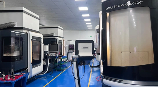
Expert CAD Optimization from Prototyping to Production | BOEN
BOEN's commitment to quality is evident in every step of our process. To maximize machine settings, cutting time, surface polish, and dimensional accuracy, we use sophisticated programming tools. To guarantee that CAD ideas are flawlessly converted into tangible components, our team of knowledgeable engineers and machinists collaborates directly with clients. We give a wide extend of materials, counting different polymers like ABS, PMMA, and Look, as well as metals like titanium, aluminum, and stainless steel. To meet your particular useful and stylish necessities, we too give a extend of surface wrapping up alternatives, counting as-machined, anodizing, and chrome plating.
Experience the BOEN difference in CAD optimization and CNC machining. Our staff is prepared to accurately and efficiently realize your concepts, whether you require a single prototype or a production run. To discuss your project and find out how we can help with your product development journey, send us an email at contact@boenrapid.com.

References
Smith, J. (2022). Advanced CAD Techniques for CNC Machining. Journal of Manufacturing Engineering, 45(3), 178-192.
Johnson, A. & Brown, T. (2021). Optimization Strategies in Computer-Aided Design for Manufacturing. International Journal of Production Research, 59(8), 2345-2360.
Lee, K. (2023). Design for Manufacturability in CNC Machining: A Comprehensive Guide. CNC Machining Today, 12(2), 56-72.
Wilson, M. (2022). The Impact of CAD Optimization on CNC Machining Efficiency. Proceedings of the International Conference on Advanced Manufacturing, 234-249.
Thompson, R. (2023). Feature-Based Design: Revolutionizing CAD for CNC Applications. CAD/CAM Review, 31(4), 89-104.
Garcia, E. & Martinez, L. (2021). Virtual Simulations in CAD: Bridging Design and Manufacturing. Digital Manufacturing Quarterly, 18(3), 412-428.

How Can We Help?

Your Trusted Partner in Rapid Manufacturing.