Custom Precision Parts for Optical Modules: Manufacturing Requirements Explained
Custom precise parts for optical modules are unique parts that are made to exact specs. The system's success in light transmission, data processing, and optical alignment is directly affected by how accurately the dimensions are measured. These parts, which include lens housings, sensor mounts, and connector kits, need to be made in a way that can achieve accuracy of just a few microns and high-quality surface finishes. Manufacturers meet the strict needs of optical uses in consumer electronics, medical diagnostic equipment, aircraft instrumentation, and car lighting systems through custom CNC machining and advanced material selection. When procurement teams understand these basic principles of manufacturing, they can work with suppliers who can provide both technical precision and reliable production.
Understanding Custom Precision Parts for Optical Modules
Modern technology runs on optical modules, which turn electrical signals into light and light into electrical signals. The precise parts inside these units decide whether a LiDAR system correctly maps the land for self-driving cars or whether a fiber-optic communication network keeps the signal strong over thousands of miles. We've seen that even a five-micron difference in the housing of a lens can throw off the alignment of the focus point, making the whole medical imaging gadget useless.
Core Components and Their Functions
Optical modules are made up of several carefully designed parts that work together. Lens tubes keep glass sights in the exact position they need to be in and keep them clean. Sensor housings keep photosensitive parts safe from outside influences while keeping the temperature stable. Mounting clamps hold fiber-optic cables in place at exact angles, and alignment pins make sure that the same assembly is done on each batch of products. For each part, there are different size issues, material needs, and surface finish standards.
Manufacturing Precision Standards
Tolerances in the optical business are higher than those used in mechanical engineering. Normal made parts can handle variations of up to 0.1 mm, but optical parts usually need 0.005 mm or less. To keep light from spreading, surface roughness standards often call for Ra values below 0.8μm. Tolerances for parallelism, perpendicularity, and concentricity become very important, especially when multiple optical lines meet in small module designs.
Industry-Specific Requirements
Temperature changes in automotive optical modules happen all the way from -40°C to 125°C, so they need materials with the right thermal expansion coefficients. Biocompatibility approvals and traceability documents are needed for medical gadget parts. When it comes to consumer technology, looks are just as important as functionality. Certifications of materials and production processes that can stand up to strict quality checks are needed for aerospace uses. These different needs make choosing a provider more like a choice matrix than just comparing costs.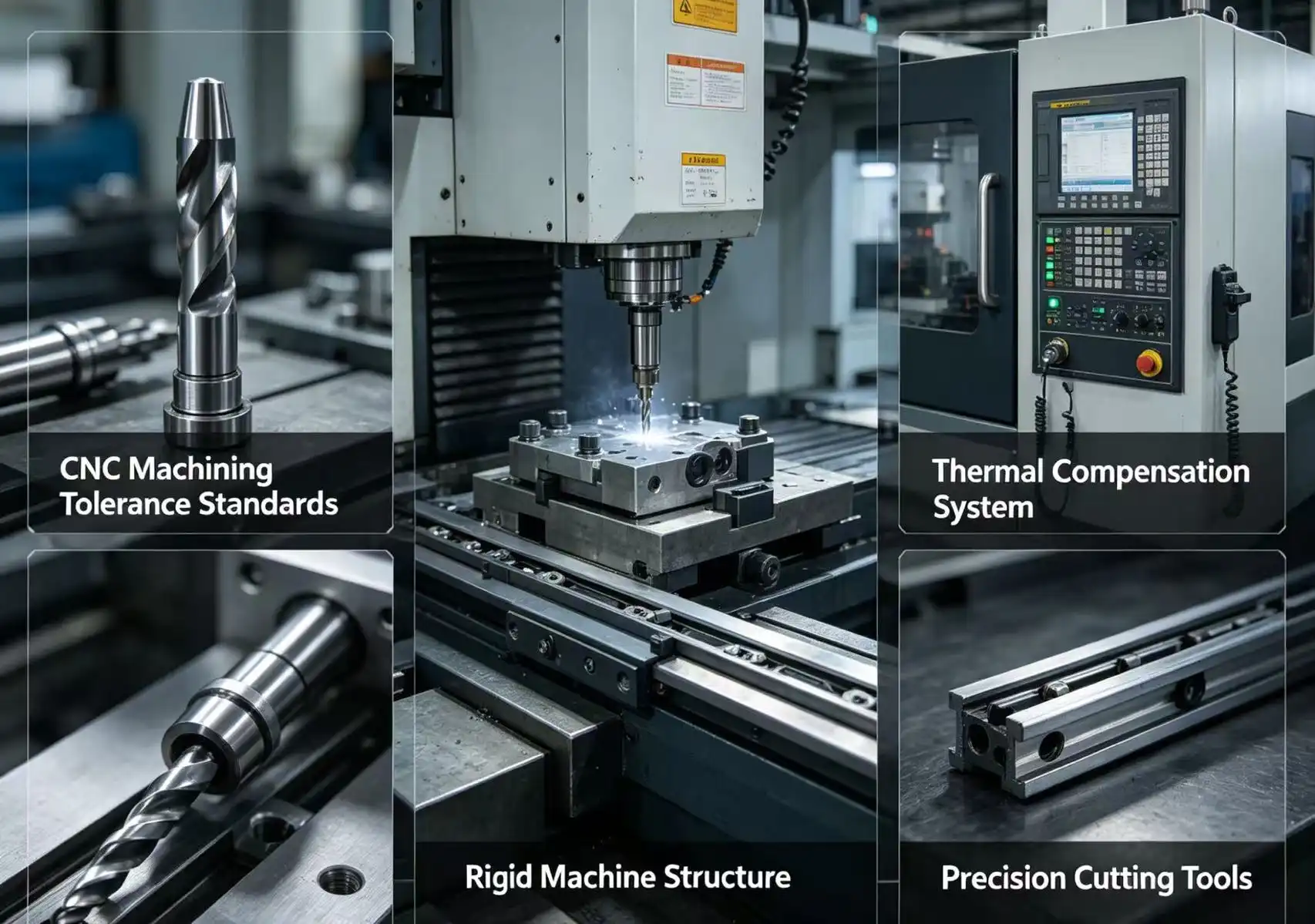
Custom CNC Machining Process Explained for Optical Parts
The need for precision in optical components makes traditional hand machining methods less useful. We've seen how hand-operated tools introduce human variation, which makes it almost impossible for batches to be consistent when limits drop below 0.02mm. Changes in temperature in the workshop cause materials to expand in ways that can't be fixed by hand in real time. Because of these problems, the optics business moved toward making things with computer control through custom CNC machining.
CNC Technology Advantages
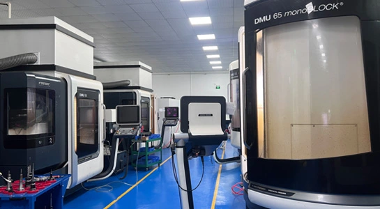
Computer Numerical Control systems get rid of mistakes made by humans by following pre-programmed tracks for tools with micron-level accuracy. Multi-axis machining centers can handle complicated shapes that would need to be set up more than once with regular machines, which cuts down on placing mistakes over time. Real-time tool wear adjustment keeps the accuracy of the dimensions throughout production runs. Temperature-controlled work areas and thermal imaging make sure that the material stays stable while it is being cut.
Engineers look at CAD files to find important measurements and surface finish needs. This is the first step in the CNC process. Material blocks are checked before they are put into fittings that are made to keep stress concentrations as low as possible. Programming the tool path makes the cutting processes work best so that heat is managed and chips are thrown away. High-pressure cooling systems keep temperatures stable and make tools last longer. Coordinate measuring machines (CMM) are used for post-machining inspection to make sure that parts meet standards before they move on to finishing processes.
Process Capabilities and Limitations
On five-axis machining centers, modern CNC equipment can position things to within 0.002mm of accuracy. Fine surface finishes can be made on metal and specialized plastics at spindle speeds of up to 30,000 RPM. But some materials are hard to machine. For example, titanium's low thermal conductivity means that heat builds up at the cutting edges, which needs special equipment techniques. To keep ceramics from microcracking, you need tools with diamond coating and slow feed rates.
CNC versatility is very helpful for small-batch production. Reprogramming only takes hours, while making an injection mold takes days. This means that ongoing design improvement is an affordable option. The time it takes to make a prototype goes from weeks to days, which speeds up the process of making a product. When the cost of tools is spread out over a reasonable number of units, production runs from 10 to 10,000 units are still cost-effective.
Materials and Tolerances in Custom Precision Parts for Optical Modules
Choosing the right material affects not only how well it works mechanically but also how it looks in custom CNC machining processes. We discovered through tests that aluminum metals like 6061-T6 are very easy to work with and are great at transferring heat, which makes them perfect for the lens housings in high-power LED assemblies. Medical camera parts that are exposed to chemicals used for cleaning won't rust if they are made of stainless steel 316. Titanium Grade 5 has the best strength-to-weight ratio for sensor mounts in spacecraft, where every gram counts.
Metal Alloys for Optical Applications
Aluminum stays the same size at different temperatures and can be coated with anodized metal that protects against rust and looks good. Its thermal expansion coefficient is very close to that of many optical glasses, which lowers thermal stress in systems that are bound together. Brass is a good material for RF-shielded optical transceivers because it conducts electricity well and is easy to machine. Beryllium copper has qualities of both a spring and the ability to control temperature, but it needs to be handled safely.
Stainless steel types are magnetically neutral, which is important for medical equipment that can work with MRIs. The material is very hard, which makes it difficult to work with tools, but it lasts a very long time in high-cycle uses like car LiDAR scanners. Titanium metals do not rust in saltwater, so they can be used in marine optical systems. They also keep their shape at high temperatures, like those found in aircraft uses.
Engineering Plastics and Ceramics
Polyetheretherketone (PEEK) can be used continuously at 250°C and has low outgassing qualities that are needed in vacuum optical systems. In yellow wavelengths, Ultem is clear, and it has better physical stability than regular plastics. Delrin has low friction coefficients for optical systems that slide and keeps tight specs even when humidity changes.
Aluminum oxide ceramics are very hard and can be used to make optical pointing surfaces that don't break down easily. Silicon nitride has a low density and a high stiffness, which makes it possible for structure parts to be both light and stiff. These advanced materials can't be machined with metal or plastic tools because they need diamond tools and special cutting settings to work.
Tolerance Management Strategies
To get micron-level accuracy, you need to use regular methods that go beyond what the tools can do. Protocols for thermal stability let materials reach room temperature before they are machined. Tool path optimization reduces the cutting forces that bend parts with thin walls. Fixture design spreads gripping pressure so that warping doesn't happen. In multi-stage machining, roughing processes ease stress on the material, and finishing passes set the final measurements.
Designers help make things easier to make by defining limits in a way that makes sense, rather than just because they can. For interference fit, a lens case that needs a bore width of ±0.005mm needs different cutting methods than one that can handle a clearance fit of ±0.02mm. Geometric dimensioning and tolerancing (GD&T) is a better way to explain functional needs than standard plus-minus specifications. This helps manufacturers improve their processes.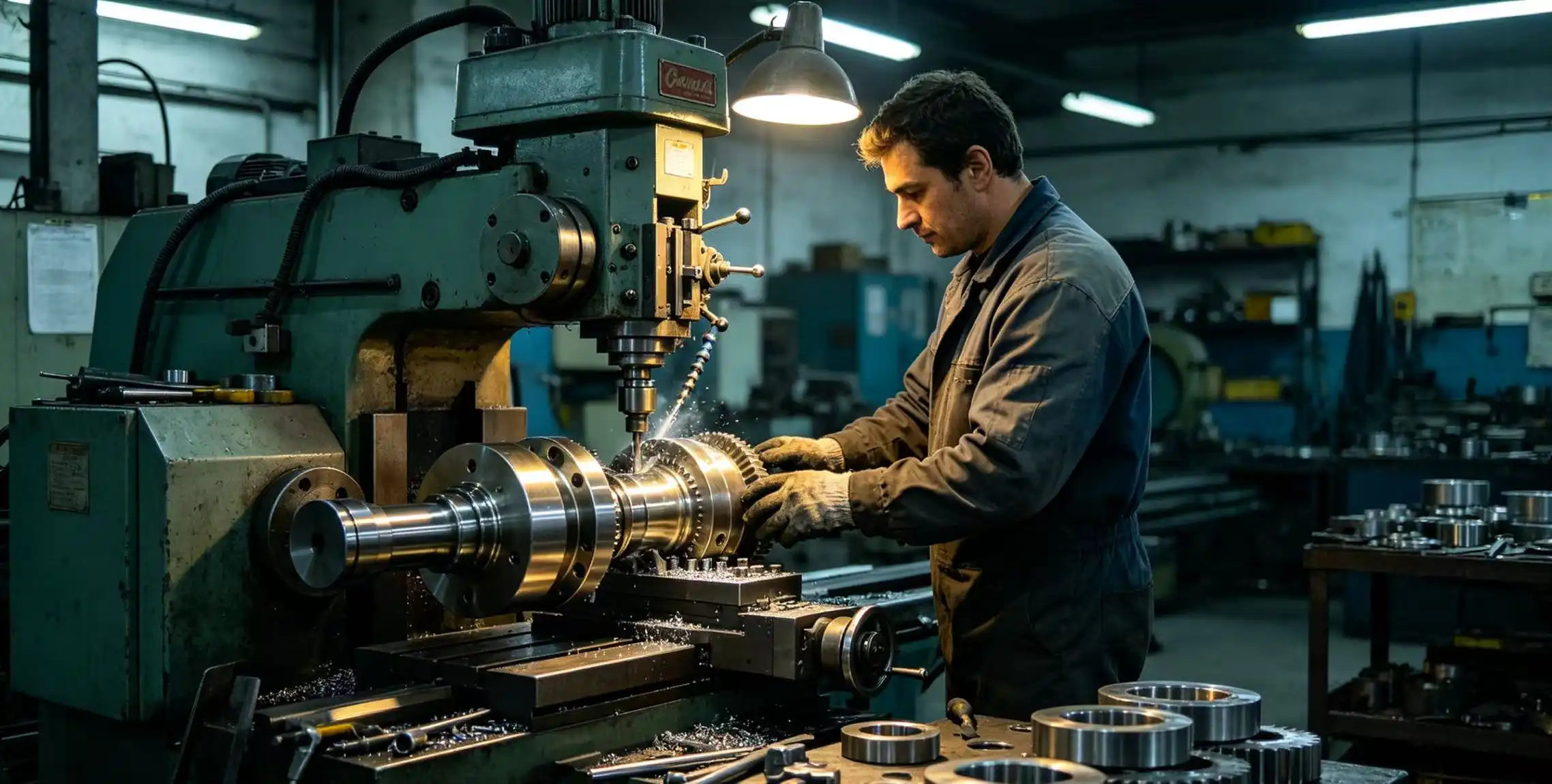
Comparing Manufacturing Methods for Optical Module Components
Choosing what to buy depends on how well the production technology fits the needs of the project. We've looked at hundreds of optical component projects where the choice of method affected both the quality of the results and the project's ability to make money. The comparison includes more than just the cost of each part. It also looks at wait times, minimum order amounts, material choices, and the consistency of quality.
CNC Machining Versus Manual Methods
Manual machining is still used in prototype shops that work with one-of-a-kind trial designs, but it isn't as reliable when making copies of complex shapes. Machinists who are skilled can make simple parts that look good, but training takes months and quality rests on the person doing the work. Once plans are approved, CNC machining will keep making the same parts over and over again, removing the batch-to-batch variations that come with human operation.
Additive Manufacturing Considerations
With 3D printing technologies like SLA and SLS, it's possible to make parts with complex internal shapes that can't be made with subtractive methods. Layer-based building, on the other hand, creates surface stepping that needs a lot of post-processing work to get optical-grade finishes. Materials don't always have the same qualities as engineering-grade metals and plastics that are used in CNC machines. Build volumes limit the size of parts, and production speeds mean that additive methods can only be used for testing or very complicated shapes where it's not possible to remove material.
Injection Molding Economics
Even though equipment costs money, injection molding is often worth it for high-volume production of more than 10,000 units. Once molds are approved, cycle times measured in seconds allow for a huge amount of work to be done. But making a mold takes 6 to 12 weeks, and if the plan changes, the mold has to be changed, which costs a lot of money. You can only choose thermoplastics as a material; metals and thermosets are not available. Accurate measurements rely on how well the mold is made, how well it compensates for shrinking, and how well the process parameters are kept the same.
Choosing the right method relies on the size and length of the project. CNC's quick turn-around and design freedom are good for prototyping confirmation. CNC's combination of speed and cost is used to make bridges that range from hundreds to thousands of units. Once there is a design freeze and enough volume to justify investing in tools, mass production changes to casting.
How to Procure Custom CNC Precision Parts for Optical Modules
A thorough description of requirements is the first step in effective buying. We suggest making thorough specs that include acceptable quality levels, material types with certifications, dimensional tolerances, and surface finish requirements, often supported by custom CNC machining for precision components. Specifications that are too vague can lead to misunderstandings and quality issues, while standards that are too strict drive up costs needlessly.
Supplier Evaluation Criteria
The technical capability review looks at the company's collection of tools, such as five-axis machining centers, CMM inspection systems, climate-controlled production areas, and special tools for optical-grade finishes. Certifications like ISO 9001 show that you have quality control systems, while AS9100 or ISO 13485 show that you know a lot about medical devices or airplanes. Ask for studies of the process's capability that show Cpk values higher than 1.33 for important measurements. This will show that the required limits are consistently met.
The review of production capacity looks at both the availability of tools and the number of skilled workers. When suppliers are almost at full capacity, it's hard for them to handle rush orders or higher volumes. Cross-training programs and written work directions show that operations are resilient and don't depend on individual machinists. Supply chain management skills allow materials to be tracked and backup sources are available in case main sellers are interrupted.
Communication and Partnership Development
Respondent contact tells the difference between suppliers who are trusted and ones who aren't. Technical help during the planning phase finds problems with how the product can be made before the tools are made, which keeps expensive redesigns from having to be done. Clear lead time predictions and tracking of milestones give faith to production planning. Long-term product success is maintained by after-sales help that deals with problems in the field or changes to the design.
Material certificates and test results show that the product meets the requirements. Mill approvals list the chemicals used and their mechanical qualities. Inspection records from a third party confirm the correctness of the measurements. Measuring the surface hardness confirms the quality of the finish. Keeping these records meets the standards for traceability in regulated businesses and provides proof of quality.
Prototyping to Production Transitions
Before committing to production numbers, successful projects often start with small amounts of prototypes to make sure the designs work. When a supplier can do both testing and production, it makes changes easier, keeps the process consistent, and gets rid of the need for requalification delays. Design for manufacturing reviews done during the prototype phase find ways to make things better so that production costs are lower without affecting how well they work.
Conclusion
Custom precision parts for optical modules need production methods that balance accuracy in dimensions, quality of the surface, performance of the material, and cost-effectiveness. CNC machining technology gives you the accuracy and freedom you need for both testing and production. It is more consistent than manual methods and has more material choices than additive manufacturing. For buying to go well, it's important to clearly define what the needs are, evaluate suppliers in a methodical way, and build partnerships that focus on expert communication and quality assurance. Choosing the right materials and managing tolerances have a direct effect on how well an optical system works, so making smart decisions is important throughout the span of a product.
FAQ
What materials work best for optical module housings?
Aluminum alloys like 6061-T6 are most often used in housings because they are easy to machine, conduct heat well, and are light. 316 stainless steel is good for medical products that need to be resistant to cleaning. Titanium Grade 5 is used in aerospace applications that need the highest levels of strength to weight ratios. PEEK industrial plastic can be used in places with high temperatures and gives designers more options than metals do.
How does CNC machining maintain micron-level tolerances?
Thermal expansion mistakes can't happen in places where the temperature is managed. Multiple setups can add up to positioning mistakes, but multi-axis equipment cuts down on those. Real-time tool wear compensation changes the cutting settings to keep the accuracy high throughout production. Conformance is checked with a CMM, and statistical process control finds trends before parts go beyond what is allowed. Fixture design keeps movement to a minimum while cutting.
Can small batch production remain cost-effective?
When compared to injection molding, CNC machining is more cost-effective for small to medium amounts because it requires less expensive tools. Setup costs are spread out over orders from 10 to 1,000 units, but the quality of each part stays the same. Rapid reworking lets you make changes to the design without having to pay a lot of money to change the mold. For many optical uses, small amounts are needed, so CNC is the best way to make things that balances quality and cost.
Partner with BOEN Prototype for Precision Optical Components
BOEN Prototype makes unique, high-precision parts for optical modules used in consumer goods, medical devices, cars, and spacecraft. Our advanced custom CNC machining skills allow us to provide micron-level accuracy and high-quality surface finishes that are necessary for optical uses. We make sure that all of our products are the same size and shape from prototypes to large production runs by using multi-axis equipment, climate-controlled production centers, and thorough CMM inspection processes. During the planning process, our engineering team works together to find ways to make things easier to make while also lowering costs without affecting performance. Our knowledge of materials includes aluminum alloys, stainless steel, titanium, industrial plastics, and specialty ceramics. This means that we can help you with the development of LiDAR sensors, medical imaging devices, or fiber-optic communication systems. As a custom CNC machining supplier with a lot of experience, we offer quality management that is ISO-certified, clear wait times, and quick expert help for the whole lifecycle of your product. Get in touch with us at contact@boenrapid.com to talk about your needs for optical components and find out how our precision manufacturing can help your project succeed faster.
References
Hecht, Eugene. "Optics: Manufacturing Tolerances in Optical Systems." Pearson Education, 2017.
Stephenson, David A. and Agapiou, John S. "Metal Cutting Theory and Practice: CNC Machining of Precision Components." CRC Press, 2018.
American Society of Mechanical Engineers. "Dimensioning and Tolerancing Standards for Optical Manufacturing." ASME Y14.5-2018.
Krar, Stephen F. and Gill, Arthur R. "Exploring Advanced Manufacturing Technologies: Precision Machining Applications." Industrial Press, 2019.
Society of Manufacturing Engineers. "Fundamentals of Tool Design: Materials and Processes for Optical Components." SME Technical Paper Series, 2020.
International Organization for Standardization. "Optics and Photonics: Preparation of Drawings for Optical Elements and Systems." ISO 10110-2021.

How Can We Help?

Your Trusted Partner in Rapid Manufacturing.